Portfolio · Robotics & Mechatronics

Jiahe Tang

Robotics & Mechatronics Builder — from RC aircraft to legged mechanisms to learning-based robot arms.

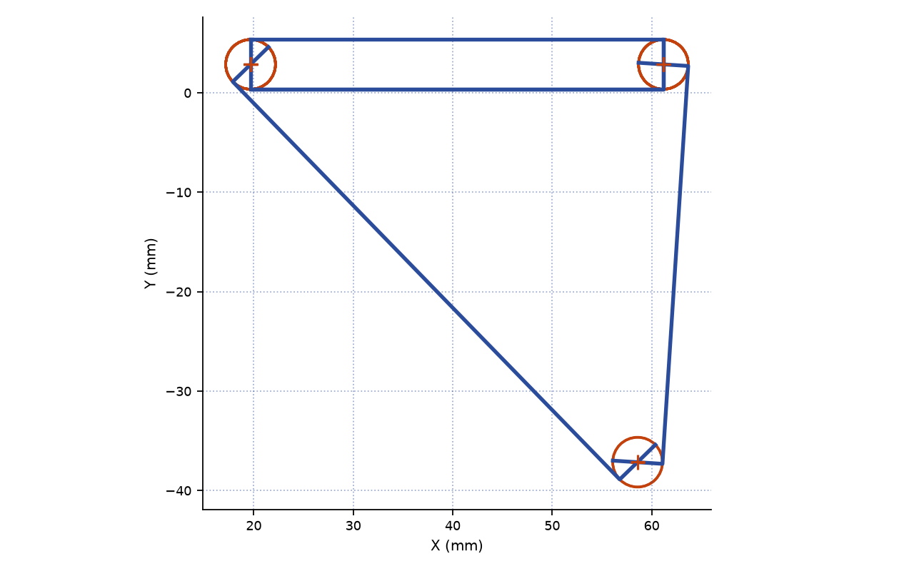
I build the whole stack: CAD, fabrication, electronics, and the software that makes it move. The linkage walking across this page is my own final-cut leg geometry — two mirrored legs running in phase, driven by one 10-tooth pinion meshing a 40-tooth ring gear per leg (4:1), each ring doubling as that leg's crank disc. One pinion drives both rings, so both crank pins are keyed alike. The faded pair half a cycle behind is the set the legs alternate with. Every outline, hole and gear tooth is drawn from the real DXF cut files. Drag it to scrub the crank.

θ 000°
Build it yourself — DXF files

9 cut parts at final scale, millimetres, laser-ready. The main body is laid out so its five holes land on the frame bar's pivots. MIT.

01 · About

Builder first, everything else second.

I got started the way most builders do — by breaking things and putting them back together better. My first aircraft was a cheap foam RC plane that barely flew; repairing it taught me more than building a new one ever could. Since then the projects have scaled up: from RC gliders to my own quasi-direct-drive actuator, from a laser-cut Jansen-linkage walker to two SO-101 robot arms trained with imitation learning.

I like working where mechanics, electronics, and software meet — designing a part in CAD, cutting or printing it, wiring the driver, and then teaching the machine to move. Every project on this page was designed, fabricated, and tested by me on a student bench, with school equipment (one 30 W laser cutter and an unreliable 3D printer) doing the manufacturing.

The through-line is simple: understand why a machine works, then build it yourself. Right now that points at legged robots and humanoids — the corner of mechanical engineering that is still being rewritten.

  • CAD & design
  • Laser cutting
  • 3D printing
  • Embedded electronics
  • Motor control
  • Imitation learning

Outside the workshop

Everything I build gets tested against the same questions: can I do it under pressure, can I do it again tomorrow, and can I do it when it isn't fun yet. Stage work, sport, and long races taught me that before the machines did.

“It just takes practice, a little bravery, and some impulsive decision-making.”

— Jiahe Tang, printed cast programme
Jiahe Tang on stage in a play, wearing an iridescent purple tailcoat, blue waistcoat and white cravat, holding a small tray
On stage in a play — a costume and a script, not a project. Same discipline either way: rehearse it until you trust it, then do it with people watching.

02 · Projects

Four builds, end to end.

Each card expands into the full engineering story: what it is, how it's built, and what broke along the way.

P·04

SO-101 Robot Arms ×2 — Imitation Learning

Flagship · Active

Two SO-101 6-DOF robot arms — a leader/follower pair — collecting teleoperated demonstrations and training manipulation policies. The most software-heavy build here, and the one where the machine stops being a mechanism and starts being a robot.

Overview

The SO-101 is the open-source successor to the SO-100 — a low-cost 6-DOF manipulator built from 3D-printed parts and serial bus servos, designed by TheRobotStudio and used worldwide as a base platform for imitation-learning research. I run two of them as a leader/follower pair: one arm is moved by hand, the joint states stream over serial, and the follower replays them — that's the data-collection rig. Recorded demonstrations then train a policy that drives the arm on its own.

Build process

  • Printed and assembled both arms; calibrated joint offsets and IDs
  • Brought up the Jetson companion computer (flashing, env, serial I/O)
  • Built a bench rig with a battery power rail and audible start/end cues for clean episode recording
  • Teleoperated the leader to record demonstration episodes
  • Trained policies on the recorded dataset; evaluated rollout success on the bench

Technical details

  • 6 DOF per arm + gripper; Feetech STS/STS-style serial bus servos
  • Leader/follower teleoperation over USB serial (pyserial-level control)
  • Jetson Orin Nano companion computer for logging and training
  • Python data pipeline: episode logging, dataset structuring, policy training
  • Battery-powered rig (8.3 V rail) for repeatable bench recording

Key learnings

  • Bus-servo ecosystems lie: reported IDs and positions can be stale or phantom — going to raw serial reads is the only ground truth
  • Clean data beats clever training: disciplined episode start/end markers improved dataset quality more than any training tweak
  • Hardware quirks (a "scrambled" arm) usually mean the wrong board or an ID artifact, not broken servos
SO-101 pair — specification
Configuration2 × SO-101, leader/follower
Degrees of freedom6 + gripper, per arm
ActuationFeetech-style serial bus servos
ComputeJetson Orin Nano
Data collectionTeleoperated demonstration episodes
Training methodImitation learning (policy trained on demonstrations)
Training episodesTBD — count from dataset log [VERIFY]
Policy success rateTBD — from latest evaluation run [VERIFY]
P·03

Jansen-Linkage Walking Machine

V2 in progress

An eight-legged walker built on Theo Jansen's linkage — the Strandbeest geometry. V1 walked and carried its own legs but the frame folded under load; v2 re-engineers the structure with proper plate design. The animated leg in the hero of this page runs the same kinematics.

Overview

Jansen's linkage turns one rotating crank into a foot path that is nearly flat and long on the ground, and lifts cleanly over the top — a walking gait from a single motor, no control software required. I built the full leg geometry in CAD from the canonical "holy numbers", then cut and assembled an eight-legged machine around a central crankshaft.

Build process

  • Reconstructed the leg in CAD from Jansen's published link lengths; sketched every bar and pin joint
  • Simulated the foot path to verify the flat stance before cutting (the hero animation runs the same solve, on my final-cut gear-train geometry)
  • Laser-cut bars and plates from plywood on the school's 30 W cutter; printed gears for the crank drive
  • Assembled v1: legs cycled and the machine walked — but the frame flexed and folded under its own weight
  • V2: redesigned side plates and bracing; finalized a clean set of nine DXF cut files

Technical details

  • Planar 11-bar linkage per leg (Jansen's "holy numbers", mm)
  • Crank radius 15 mm; fixed pivots on a 38 × 7.8 mm ground link
  • Simulated foot path: ≈621 mm stride, ~85% of it within an 8.5 mm ground band
  • Legs paired in phase opposition on a shared crankshaft
  • Gear-driven crank; structure in laser-cut plywood + printed connectors

Key learnings

  • Geometry is free; structure is not — the linkage was right, the frame was the failure
  • Sketch-grade CAD ≠ cut-ready CAD: joints tangent to bar edges sever parts on the cutter
  • Duplicate stacked lines in DXFs burn edges — a clean-up pass is part of design, not an afterthought
Jansen walker — specification
Legs8 (4 × 2 paired)
LinkageJansen 11-bar, canonical proportions
Stride (per crank rev, simulated)≈621 mm at final cut scale (≈565 mm on the 10/11 A2 layout)
Stance flatness (simulated)~85% of the stride within an 8.5 mm ground band
DriveGeared crank, DC motor
StructureLaser-cut plywood plates, 3D-printed gears
GaitAlternating tetrapod, phased by crank position
StatusV1 walked, frame failed → V2 plate design in progress

Source & files

The A2 gear-train animation and its kinematics script are open source under the MIT licence: a self-contained pack with the leg geometry, the A2 gear train, the DXF part dimensions and the render script that produced the video above.

Download jansen_sim_pack.zip — 153 KB, MIT

P·02

Quasi-Direct-Drive Actuator

Design stage — not yet built

A custom quasi-direct-drive actuator: an outrunner BLDC driven by an open-source VESC speed controller, with magnetic encoders sensing shaft angle for closed-loop position control. Intended as the muscle for future legged robots — the same actuator philosophy used by modern humanoids. This one is still on the drawing board.

Overview

Quasi-direct drive means the motor spins fast with low gearing (typically 6–10:1), so the rotor's own inertia can back-drive the gearbox. That makes the joint compliant and force-controllable — you can push a QDD joint and it gives, which is why research humanoids use them. Instead of buying one, I am building one: BLDC + VESC + encoders + a 3D-printed planetary gearbox of my own design.

Build process

  • Sizing the motor and gear ratio against a robot-knee torque budget
  • Generating parametric gearbox plates and gear DXFs/STLs for printing
  • Wiring the VESC open-source controller and configuring FOC over USB
  • Adding magnetic encoder sensing on the output shaft for position feedback
  • Then bench testing: step responses, torque limits, thermal behaviour

Technical details

  • Outrunner BLDC motor — model not yet chosen
  • VESC open-source ESC running FOC current control
  • Magnetic encoders: motor-side + output-shaft angle
  • Single-stage planetary reduction, 3D-printed gears
  • Closed-loop position control on the output shaft

Key learnings

  • Back-drivability is a design choice, not a spec-sheet number — ratio selection is the whole game
  • Printed gears mesh fine at these torques if you print them big enough and compensate hole tolerance
  • Open-source motor control (VESC) collapses the electronics barrier: the hard part is mechanical
QDD actuator — specification
ArchitectureBLDC + single-stage planetary + output encoder
StatusDesign stage — no measured figures yet
Reduction ratio (target)6–9:1, to be fixed once the motor is chosen
ControlVESC FOC + position loop on magnetic encoder
Gearbox3D-printed planetary, custom parametric design

Live: QDD torque calculator

τout = Kt × I × G × η — play with the motor constant, current, and gear ratio to see why QDD joints land at 6–9:1.

0.101 N·m/A
10.0 A
7.0:1
5.36 N·m output torque
≈ 1234 no-load speed · sane QDD territory

Estimates use a simple planetary-efficiency heuristic — this is a design-space toy, not a datasheet.

P·01

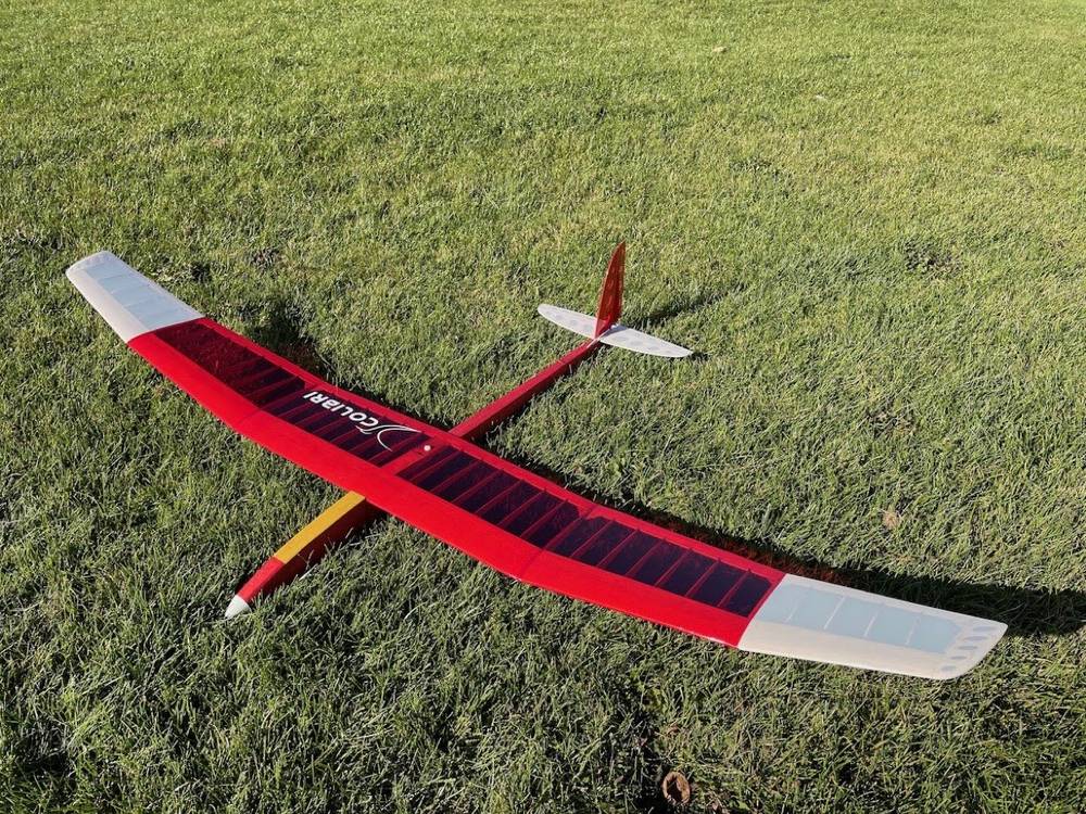
RC Glider — Colibri 1500

Flying · EE testbed

A 1500 mm wingspan RC glider — my route back into building. Started as a repair of a cheap foam plane, became a full build from a laser-ready plan set, and then became an Extended Essay testbed for materials testing.

Overview

The Colibri is a classic 1.5 m RES-style thermal glider. I built it from the published vector plan set — cutting parts, assembling the fuselage and tail, and finishing the wing with its carbon spar. Where my first foam plane was a repair job that taught me why things break, the Colibri was a clean-sheet build that taught me why things fly: trimming, center-of-gravity, and how spar stiffness buys launch survival.

Build process

  • Sourced the Colibri 1500 plan set (vector CAD + PDF build guide)
  • Cut and assembled structure; mounted radio gear and control linkages
  • Used the glider as the experimental platform for my Extended Essay: spar-material stiffness testing
  • 3D-printed a display model of the airframe from the same geometry

Technical details

  • 1500 mm wingspan RES-style thermal glider
  • Carbon-spar wing; balsa/foam structure per plan set
  • Standard RC gear: receiver, two servos on the tail, launch by hand/bungee
  • Extended Essay: three-point bending tests of spar materials

Key learnings

  • Repair is the best teacher — every failure isolates one design decision
  • Materials testing on paper ≠ in the air: measured stiffness only matters through the loads it actually sees
  • Building from someone else's plans, then deviating where you understand why — that's the growth path
RC glider — specification
ModelColibri 1500 (published plan set)
Wingspan1500 mm
TypeRES thermal glider
SparCarbon spar (EE test subject)
ThrustUnpowered glider — hand/bungee launch
Flying weight[VERIFY] from build log

Cut your own body

The body is one flat panel, and these are its walls. Cut the panel twice and the walls once, and the flat surface becomes a solid 3D body with a hollow middle. Broken carries the teeth: a comb cut into every side of its outline, and the walls are rectangles with the matching slots along both long edges, so each one drops onto the teeth of both panels at once. Tell it the thickness of your material and every tooth is cut to match it. Straightened out, that comes to six rectangles — cut each one as many times as its count says.

The six rectangles

One rectangle for every length the body's sides come in — the count is how many to cut. Their length is fixed by the body: a wall has to be exactly as long as the side it goes on.

Shape

How far apart the two panels sit — how deep the hollow is. 1000 mm (1 m)

Broken's teeth

Cut into every side of the body's outline. The material's thickness is how deep each tooth bites: a tooth crosses the wall's whole thickness and stops flush with its far face, and the notch it drops into is cut one thickness deep. Count is how many teeth each side tries for — it also sets how wide they are, so a long side wants a bigger count. The rectangles carry the matching slots, and the other panel has the same teeth, so one rectangle joins both. A short side gets fewer teeth than you ask for.

Holes

Sheet layout

Lay every part out on one stock size so nothing is cut that does not need to be: the sections you built plus the kit parts.

Top: the body, with its own teeth cut into every side of its outline — to scale. Middle: one tooth from above, drawn at the material's own scale, because a 3 mm bite on a 1.26 m body is a hairline: the body's tab crosses the wall and stops flush with its far face. Bottom: the six rectangles, one row each so that six is what you count; the slots are drawn exaggerated there. The cut sheets are always true size.
The layout: every part placed on the stock you chose, rotated where that saves a sheet. The rectangle is the stock edge, not a cut.

03 · Skills & Stack

Tools I actually use.

  • CAD

    CORE

    Part and assembly design, DXF export for laser cutting, parametric gearbox generation.

  • Laser cutting

    CORE

    Cut-file preparation, kerf and stacking cleanup, plywood mechanism design.

  • 3D printing

    CORE

    FDM part design and iteration — gears, plates, mounts, display models.

  • Soldering & wiring

    CORE

    Power rails, servo harnesses, connector standardization on the bench rig.

  • Embedded & control

    GROWING

    Serial bus servos, VESC/FOC motor control, encoder feedback, Python pyserial.

  • Python & data

    CORE

    Episode logging, dataset tooling, kinematic simulation, experiment analysis.

  • Imitation learning

    GROWING

    Leader/follower demonstration collection, policy training, rollout evaluation.

  • Jetson / Linux

    GROWING

    Board bring-up, environments, serial I/O on Orin Nano.

04 · Contact

Build things with me.

Want to talk robots, actuators, aircraft, or collaboration on an open build? Email is fastest.

  • Email: TODO-SET
  • GitHub: TODO-SET

This block fills in once real handles are confirmed — see README.

Falls back to your email app (mailto) — swap in Formspree when this goes live (README §Deploy).